Build power system reliability
Egon Hillermann
Building Products
ABB Electrification Products Division
Facility managers seek to isolate electrical outages to the smallest possible area. Current protective systems often don’t do that. Read this article to learn how to build power system reliability with breaker coordination that limits faults to a branch closest to the fault while protecting the rest of the network.
Imagine the plumbing system in your home developing a leak in an outside spigot that requires attention. Instead of being able to turn off a stop valve controlling that spigot, your only option is to turn off the water main for the whole house. That would clearly be unacceptable.
Yet that’s basically the situation in the power-distribution systems of many facilities. These systems often respond to faults by de-energizing a large number of branches rather than isolating the fault closest to the load where the fault occurred.
What are the costs of these kinds of large outages in critical-load facilities? The average cost of a single data-center outage is about $730,000, according to a 2016 study by the Ponemon Institute. Among the more than 60 data-center operators surveyed, the costliest outage resulted in a loss of about $2.4 million.
In our increasingly digital world, many organizations find themselves at serious financial risk due to power outages. A recent example was the Delta Airlines data center outage that grounded about 2,000 flights over three days, costing the company $150 million. This is an all-in cost that includes not only data and equipment damage, and productivity losses, butalso legal and regulatory impact, and impact on brand and reputation.
Breaker coordination provides an additional line of defense against these unplanned and expensive power outages.
Coordinated protection
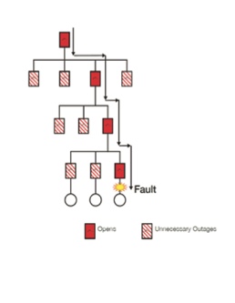
Without breaker coordination
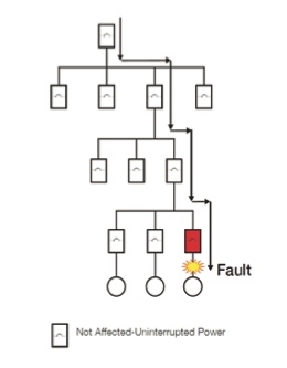
With breaker coordination
Breaker coordination refers to the use of breakers, specifically the latest electronic trip breakers, to isolate electrical problems. When a fault happens, the closest overcurrent protective device opens either a breaker or miniature circuit breaker, ensuring that any faults don’t cascade upstream. The methodology increases uptime by limiting power outages to the branch closest to the fault of an electrical system where a problem occurs without knocking out other areas of the system.
In addition to limiting an outage to the shorted or overloaded branch circuit and reducing nuisance tripping, breaker coordination makes it easier for electricians to investigate causes of faults, identify underrated or overloaded equipment, and make corrections. Power can typically be restored faster than when upstream breakers are tripped, especially if an entire panel board has been taken down.
Faster response
UL defines breaker current limitation as a breaker that interrupts and isolates a fault in less than one-half of an Ac cycle, which takes 8.3 milliseconds. A typical zero-point extinguishing breaker will interrupt a fault, but it will not isolate the energy. The breaker allows an arc to be present between the open contacts until the Ac wave form crosses zero (as long as 8.3 milliseconds). When the wave form crosses zero, the potential energy is zero and the arc (fault) naturally extinguishes. in comparison, new state of the art current-limiting miniature circuit breakers open and extinguish the arc in less than a quarter cycle, or 4 ms.
Recent improvements in circuit breaker technology, including current-limiting miniature circuit breakers, have pushed the response time and tripping characteristics of electronic trip breakers to the same level as fuses.
The following graphs provide a visual reference of the improved protective response with breaker and current-limiting miniature circuit breaker coordination. in the first graph, the time current curves show circuit breaker performance characteristics on a logarithmic scale. it shows a downstream Branch Breaker B and Main Breaker A without coordination. note that there is no separation between the curves. The branch breaker will react to a fault while the main breaker will also open and de- energize all other downstream circuits.
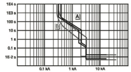
Chart 1: No coordination
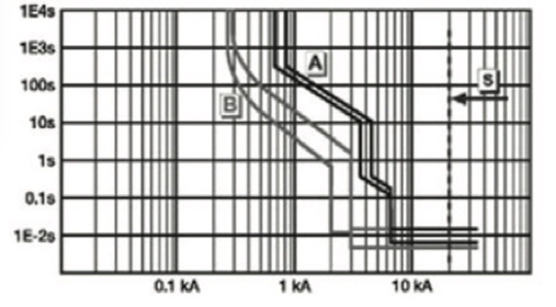
Chart 2: With coordination
Chart 2, is a graphical representation of a downstream branch breaker (B curve) and a main breaker (A curve) with selective coordination. The separation between the curves means that the branch breaker will react to a fault faster while the main breaker remains closed and energized. Even at high short-circuit currents the branch breaker reacts below the threshold of the main breaker.
Conclusion
Whether in new designs or retrofits, incorporating selective breaker coordination typically requires some additional costs and new electrical-system components. in critical load applications, the potential risks and losses resulting from a system failure may easily justify the incrementally higher design and construction costs. Facility managers should determine whether the added expense will be offset by the enhanced reliability.
For optimum reliability, today’s electrical systems require multiple levels of protection. Selective coordination is often overlooked as a potentially valuable element in enhancing the system’s reliability. Managers of facilities that require near-perfect power reliability should consider a selective coordination study to evaluate the reliability advantage this technology can provide.