

Beyond the instrument transformer: How sensors and protection relays simplify digital switchgear
Conventional instrument transformers have long limited switchgear design. Working together, instrument sensors, modern protection relays, and IEC 61850 communication remove many of those limits, helping OEMs build switchgear that is safer, more compact, and easier to standardize, with protection that keeps their customers’ operations running.
Medium-voltage switchgear is evolving beyond conventional approaches to electrical measurement, protection, and automation. While current transformers (CTs) and voltage transformers (VTs) have served as the foundation of protection systems for decades, advances in instrument sensors, multifunction protection relays, and IEC 61850 communication are enabling safer, more flexible, and increasingly digital protection architectures.
The true transformation lies in how these technologies work together, extending the benefits of modern measurement technology into advanced protection applications while simplifying switchgear design.
The evolution of instrument sensors
Modern instrument sensors are changing how electrical quantities are measured. Compared with conventional instrument transformers, they offer improved safety, a smaller footprint, simplified wiring, and greater installation flexibility. Rogowski coil-based current sensors eliminate magnetic saturation and open-CT secondary hazards, while resistive and capacitive voltage sensors eliminate ferroresonance concerns.
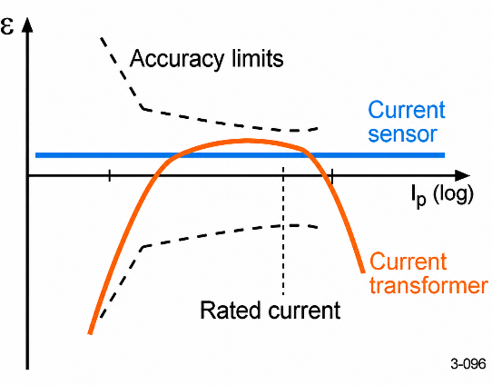
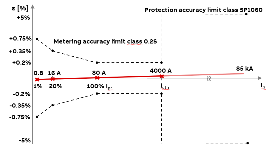
A key advantage is their wide linear measurement range and combined metering and protection accuracy. Current sensors can offer combined accuracy classes such as 0.2S/5P1060, maintaining specified performance from low-load currents through high fault-current levels. Similarly, voltage sensors with combined 0.2/3P accuracy classes support both metering and protection applications.
Unlike conventional CTs, which may saturate during faults, Rogowski coil-based sensors preserve current waveform fidelity across their specified operating range. This supports dependable fault detection while retaining harmonic and transient information for disturbance analysis and power-quality monitoring. Their wide measurement range also enables a single sensor design to serve multiple switchgear ratings, simplifying engineering and standardization.
However, the real value of sensors extends beyond improved measurements. Their potential is fully realized when combined with protection relays capable of applying these measurements to advanced protection schemes, including applications traditionally dependent on conventional CTs and VTs.
Modern protection relays: Expanding sensor applications
Historically, sensor adoption in certain protection schemes has been limited, particularly in differential protection, where currents measured at multiple locations must be accurately compared.
Modern multifunction relays, such as ABB’s Relion family, are helping overcome these limitations through flexible analog input hardware, advanced measurement scaling, and protection algorithms capable of processing both conventional CT/VT and low-energy analog (LEA) sensor signals.
By normalizing these measurements into common electrical quantities, relays enable fully sensor-based or hybrid protection architectures, allowing engineers to choose the most practical measurement technology for each application.
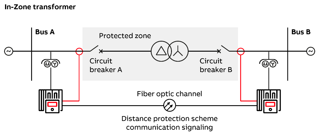
Transformer differential protection (87T) and restricted earth fault (REF)
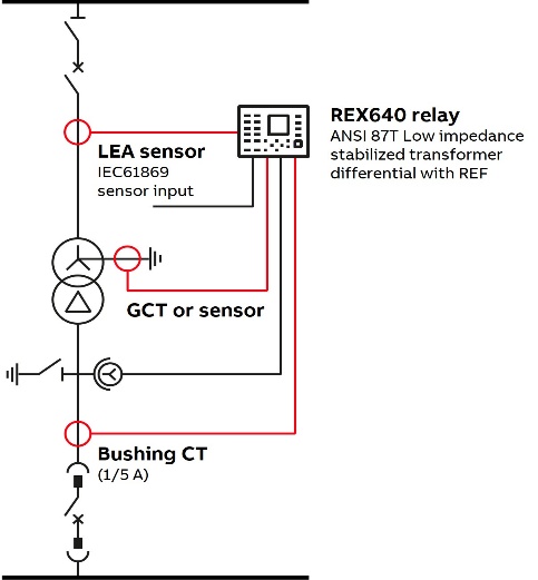
Transformer protection provides a compelling example of this flexibility. In many installations, conventional bushing CTs remain the practical choice on the high-voltage side of a power transformer, while compact current sensors can be more easily integrated into medium-voltage switchgear on the opposite side.
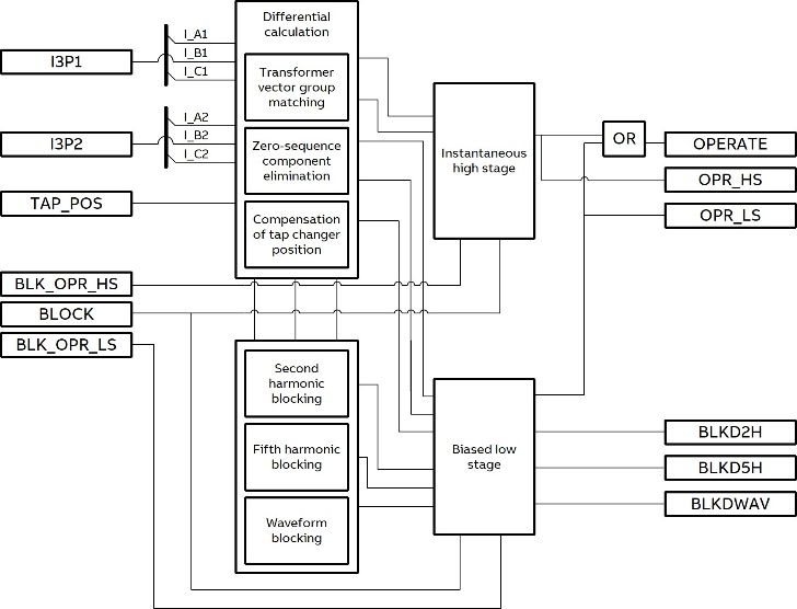
Modern relays can combine these two measurement technologies within the same differential protection zone. The relay normalizes current measurements, compensates for transformer ratios and winding phase displacement, and compares the currents entering and leaving the transformer to detect internal faults.
Biased differential characteristics provide stability during external faults, while harmonic restraint or blocking helps prevent unwanted tripping during transformer energization and overexcitation. Restricted earth fault (REF) protection adds sensitivity for ground faults near the transformer neutral.
This hybrid approach enables sensor adoption without requiring the replacement of existing instrument transformers or compromising established protection principles.
Line differential protection (87L)
The same flexibility extends to line and cable differential protection, where relays at opposite ends exchange current measurements through a dedicated communication channel.
With appropriate measurement scaling and compensation, conventional CTs and sensors can be used at different ends of the protected line. Advanced line differential functions can also accommodate transformers within the protection zone by compensating for their winding configuration and phase displacement.
This provides greater design flexibility for installations where existing protection infrastructure must coexist with newer sensor-equipped switchgear.
Low-impedance bus differential protection (87B)
Bus differential protection demonstrates an even greater opportunity to simplify switchgear architectures by combining sensors, multifunction relays, and digital communication.
Traditionally, low-impedance bus differential protection may require dedicated CT cores, extensive secondary wiring, and additional bay-level intelligent electronic devices (IEDs). These requirements can increase panel space, equipment costs, and engineering complexity.
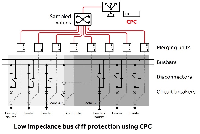
In a digital architecture, existing sensor-compatible relays or merging units at incomers, feeders, and bus-ties digitize current measurements and publish them over an IEC 61850 network using Sampled Values.
A centralized protection and control (CPC) system, such as ABB’s SSC600, receives these measurements and performs low-impedance bus differential protection, including dynamic bus-zone selection and selective tripping of affected bus sections.
By leveraging shared measurement and communication infrastructure, this approach can eliminate the need for dedicated bus protection measurement devices, reduce secondary wiring, and simplify protection-zone configurations.
For switchgear OEMs, it offers an opportunity to standardize protection hardware while delivering sophisticated bus protection with fewer components.
Cost-effective alternatives for bus protection
Although low-impedance bus differential protection can be implemented using sensors, conventional high-impedance bus differential schemes are not directly compatible with LEA sensor outputs.
For distribution switchgear applications where dedicated differential protection is not required, Zone Selective Interlocking (ZSI) and Directional Comparison Blocking (DCB) offer practical, cost-effective alternatives.
Zone Selective Interlocking (ZSI) is well suited for radial distribution systems. For a downstream feeder fault, the feeder relay sends a blocking signal to the upstream relay, allowing the feeder to clear the fault selectively. For an internal bus fault, no downstream blocking signal is received, enabling fast upstream tripping. These signals can be exchanged through hardwired connections or IEC 61850 GOOSE messaging.
Directional Comparison Blocking (DCB) uses directional overcurrent elements (ANSI 67) and exchanged blocking signals to distinguish internal from external faults. For external feeder faults, the appropriate relay sends a blocking signal to prevent unnecessary bus tripping. For internal bus faults, the absence of blocking permits tripping after a short coordination delay. This approach is particularly useful in networks with multiple sources or bidirectional fault currents.
While both schemes offer economical sensor-compatible alternatives, they are not functionally equivalent to differential protection. Low-impedance bus differential (87B) remains preferred where superior sensitivity, speed, and selectivity are essential, especially in systems with inverter-based resources (IBRs) and limited fault currents.
The building blocks of digital switchgear
These examples illustrate how modern measurement and protection technologies are moving switchgear beyond conventional hardwired architectures.
Three complementary technologies form the foundation of this transformation:
- Low-energy analog (LEA) instrument sensors provide compact, accurate, and linear current and voltage measurements, improving safety while enabling equipment standardization.
- Multifunction protection relays combine flexible hardware with software-based protection algorithms, allowing a common platform to support sensor-based, conventional, and hybrid protection schemes.
- IEC 61850 communication enables current and voltage measurements to be shared through Sampled Values, while GOOSE messaging supports high-speed protection and interlocking signals.
Together, these technologies enable more flexible, scalable digital protection architectures that reduce dependence on dedicated measurement devices and extensive point-to-point wiring.
For switchgear OEMs, this translates into simplified engineering, fewer hardware variants, and more standardized designs. For utilities and industrial customers, it means improved safety, greater protection flexibility, and easier system expansion.
Ultimately, digital switchgear is not simply about replacing conventional instrument transformers with sensors. It is about bringing together advanced measurements, intelligent protection relays, and standardized communication to deliver smarter, simpler, and more adaptable power distribution systems.
Related reading: Built to perform: Advanced instrument transformers raise the bar for OEMs · Next-generation, software-defined devices deliver business benefits for OEMs and end-users
Author

Shantam Chavan, OEM Product Marketing Specialist · ABB Electrification Business
Shantam supports product homologation, marketing, and business development for ABB’s digital protection and automation portfolio in the United States, driving the adoption of advanced digital solutions across utilities, data centers, renewables, and industrial power systems. He brings more than eight years of experience in application engineering, product development, and go-to-market strategy for medium-voltage protection and automation systems. He holds a bachelor’s degree in electrical engineering from the University of Mumbai and a master’s degree in electric power systems engineering from North Carolina State University.