
Circuit breaker trip curves: A guide for panel builders
Circuit breaker trip curves are a critical but often confusing characteristic of miniature circuit breakers. Knowing the basics of trip curves can ensure selecting the lowest-cost breaker that will provide the needed protection without nuisance tripping.
To the average consumer, circuit breakers are basic on/off devices that trip when they detect incoming current above the rated threshold. Panel builders, however, understand that breakers operate in a far more sophisticated way considering multiple variables: variables that can be represented graphically in a trip curve that shows the range of conditions that will initiate a trip.
Selecting the optimum miniature circuit breaker (MCB) is critical to helping ensure proper protection, with minimal or no nuisance tripping, at the lowest possible cost. Matching a breaker to an application requires an understanding of the basics of trip curves.
Molded-case versus miniature circuit breakers
Almost every electrical-protection device operates based on a simple formula: If THIS, then THAT. Some large, molded-case circuit breakers can be adjusted to adapt the breaker to the application, reacting to THIS variable with the appropriate THAT response.
This adjustability enables panel builders to select a molded-case breaker with the required specifications – plus a “safety factor” to account for application unknowns or future equipment changes – and then “tune” the breaker once it’s in use.
MCBs, on the other hand, operate based on only two parameters that cannot be adjusted: overload and short-circuit. Even with just these two basic parameters, though, breaker buyers have a broad selection of MCBs that could potentially meet their application requirements. Selecting the appropriate breaker includes considering not just features like amperage, voltage, and interrupting rating, but also trip curves.
Trip curve basics
Most protective devices have a defined trip curve, also referred to as a time/current curve, that describes their behavior. The curve is represented in a graph showing how the breaker will respond to changes in current, basically the high- and low-current thresholds, that will cause a trip.
The optimum trip curve balances overcurrent protection and machine operation. A fast-acting trip curve will do an excellent job of protection, but at the cost of frequent and costly nuisance tripping (mostly due to inrush currents of motors and transformers). A breaker with higher trip points will better keep the process up and running.
Trip curves are defined by IEC standards 60898-1 and 60947-2. The curves represent two different trip functions: thermal and electromagnetic. The thermal section (top/red area of the chart) that responds to overloads typically consists of a bi-metallic strip. The thermal trip unit responds relatively slowly and is consistent across all trip curves.
The short-circuit section (bottom/grey) relies on a magnetic coil or solenoid that opens when the overcurrent’s design limit is reached. This section of the breaker responds within milliseconds. This characteristic of the trip curve has no counterpart on the UL side.
The concept of trip curves originated in the IEC world, and the alphabetic code used to categorize MCBs carried over from IEC standards. They define the lower and upper thresholds for tripping (no-trip threshold and trip threshold). The trip-curve graph shows the tolerance band within which manufacturers can set the individual tripping point of their breakers.
IEC trip curve types
The characteristics of the magnetic/short-circuit trip unit and applications of each curve, from most- to least-sensitive are:
Z: Trips at 2 to 3 times rated current. Suitable for highly sensitive applications, e.g., semiconductor devices.
B: Trips at 3 to 5 times rated current.
C: Trips at 5 to 10 times rated current. Suitable for medium inrush currents.
K: Trips at 10 to 14 times rated current. Suitable for loads with high inrush currents, mostly for use with motors and transformers.
D: Trips at 10 to 20 times rated current. Suitable for high starting currents.
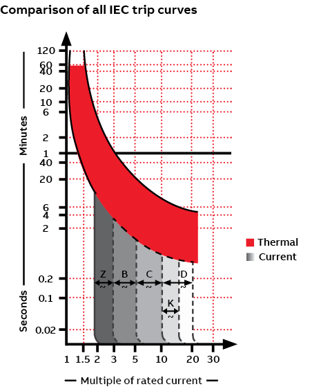
Referring to the graph above, you can see that higher currents trigger more rapid trips.
The ability to tolerate inrush current is an important consideration in trip-curve selection. Certain loads, notably motors and transformers, experience a momentary change in current – the inrush current – at contact closure. Faster protective devices, like a B-trip curve, would see this inrush as a fault and open the circuit. For these types of loads, trip curves with a higher magnetic tripping point, either D or K, can “ride through” the momentary inrush of current, protecting the circuit without nuisance tripping.
Choosing the right trip curve
Experienced panel builders can often identify the appropriate trip curve for various applications but may require some trial and error to arrive at the optimum breaker. For many panel builders, though, the best approach may be to consult with your device manufacturer or distributor. Provide them with the details of your application, and they should be able to recommend the right miniature circuit breakers to meet your needs.
See related blog post “Choose enhanced breaker and controller options to build more-competitive panels”.
Author
Thomas Weinmann
Senior Product Marketing Manager, ABB Electrification Business. Thomas brings over 33 years of experience at ABB, specializing in electrical protection and control products, circuit protection devices, and low-voltage electrical systems for industrial and OEM applications. He holds a Bachelor’s Degree in Mechatronics, Robotics, and Automation Engineering from the University of Applied Sciences, Esslingen, Germany.

